
Activity Feed › Discussion Forums › Software, CAD & Mapping › C3D 2020 surface boundaries and
C3D 2020 surface boundaries and
Posted by jitterboogie on February 14, 2022 at 4:57 pm..the artistic license Autodesk takes for the surface.
Is there an easy workflow based way to avoid the application from just plopping down its surface (previous employer we used TBC to create the area for the surface and import to C3D) area definition and not have to outsmart the program by collection of data beyond where I care about for the deliverables?
TYIAFAI.
I am no master drafter, but I’m almost competent.
Almost.
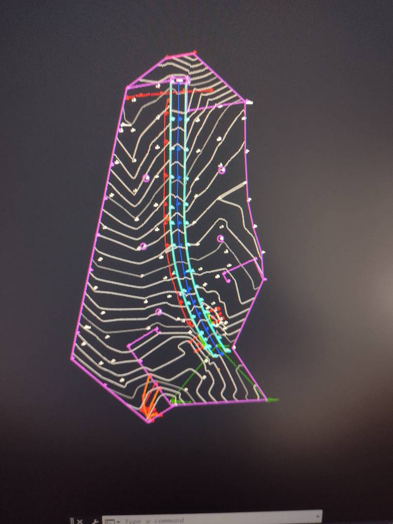
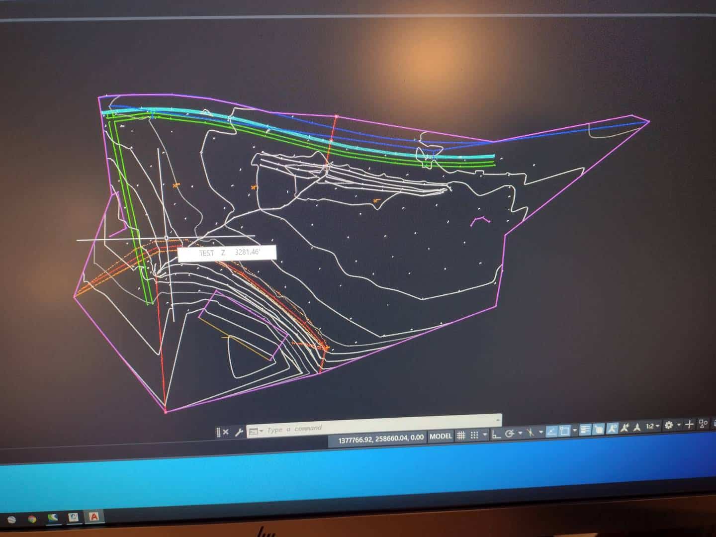
And FWIW this is the auto line work from my field points after import into the drawing.
rover83 replied 2 years, 1 month ago 12 Members · 20 Replies- 20 Replies


I’m not certain what you are asking for – but possibly “non-destructive breaklines” is your answer. You can also draw a polyline border, import that as surface data, and the area of the surface will be limited to it.
BTW – neither google nor I recognize the acronym “TYIAFAI”.

@norman-oklahoma
Thank you in advance for any Information
I daily find new things and lots of them I don’t use but find interesting.
The whole C3D thing is like a ball of yarn to me and I’m an adolescent kitten losing my mind with it.

If I understand you correctly, you want to manipulate the surface boundary to only show contours where your deliverable is.
To do this, you can draw a polyline (PL) around your area of concern and then add it to the surface as a boundary.
T. Nelson – SAM, LLC@norman-oklahoma
Yeah I guess so…
So I have to tell it I want more space than the fences I didn’t go past and the one point in nowhere isn’t part of the boundary I WANT, so Introducing a second poly line boundary to augment what it’s created from my data.
Thank you.
I read that in the C3D help and wondered why can’t I just select the are before and ‘buffer’ it and realized that my GIS brain was getting in too deep with the survey drafting CAD world….
Oh the pain I make myself is so fun at times….
Woohoo!

It’s been my experience that creating surfaces isn’t substantially different in Civil 3D than it was in DCA or Softdesk or LDD or Eagle Point, or different than it is in Carlson. Surfaces will extend out as far as your data, and if you want it cut back from that for some reason, you need to define the limits.
It’s just at my lack of knowledge of the tools, and I appreciate all the feedback.
In my mind, and I’m not kidding,
I’m planning on over collecting to make the surface software do what I did, and not amplify my mistakes…
???? ???? ????

We conduct oddly shaped topos all the time in Civil3d and rarely use boundaries. We just turn the TINN on the delete the unwanted triangles. This is typically a very quick process.

@wa-id-surveyor Ditto. Use a crossing window to delete the triangles you don’t want. Very quick and less fuss than making a boundary. Also make sure you set your maximum triangle length in Properties (this too can be done after the fact).
If you want to make an area-limited surface, I would tend to create a Point Group with only those points, again using a crossing window to add those points to a new Point Group. Then create a surface from that Point Group only.

What is your problem or question? Hard to tell from your screen views.
C3D has settings for break lines in the figure prefix database, surface settings for length of triangle. Remember there break lines need to be added to a surface, they don??t automatically get into the definition of your surface.
I appreciate the comments and suggestions. I’m realizing that I’m having flashbacks tomy LDP EUTOPIA, and now I’m always in a small cut out of a bigger undefined area.
I’m used to using TBC to swap sides and clip out triangles I don’t want/need.
I am very familiar with the point grouping, in fact, have gotten very dependable results dropping the points like WFH and any other random high point I don’t need for a surface, and when tweaking the break lines throwing in a few extra free GND( we call these TSZ, DONT ASK) by including any FCL or UPD-X as they are never used for vertical and always have a true surface elevation that can be used for infill.
The C3D template is all different from what was using so much so I had to slow down the friggin command line to stop auto selection of the wrong things I didn’t want to short cut by typing.
I’ll have to get more screen time on my days off to get a really good handle on how I can best represent the AOI an engineer throws at me without missing the essential details, but not go outside their scope and be a snide schmuck for saying…well, you should have made the AOI bigger, and I would have picked that up too….
All said, I love this site, and thanks for the advice and guidance.

As others have said, you can draw a polyline topo border and set that as an Outer boundary. I also use building and retaining wall polylines as Hide boundaries.
I prefer to set boundaries and breaklines rather than editing the tin lines. Well, I prefer to use Carlson, but when forced, this is how I do it in C3D
@wa-id-surveyor @frozennorth
The place I work now, when I first started, I made the mistake of offering up that I never use boundaries to create a surface in C3D. The looks on the faces of the other people made me realize I need to keep my mouth shut. They were appalled to say the least.
I chalked it up to their newness with C3D and their background with Carlson. I say that only because I used boundaries with Carlson because I did not like editing triangles within it. For me it was faster to create a shrinkwrap, then modify that polyline to follow the exact outer limits that I knew I would want.
Of course I can’t keep my mouth shut forever. I still have them shaking their heads whenever I suggest something avant-garde.
I’m just wondering why you wouldn’t start with boundaries, and then edit your tin for inevitable mistakes and/or just weird things the software does.
I’m sure you know, since I believe that you’re much more skilled with CAD than I am, that it takes maybe a minute to define your boundaries and breaklines. But I get that you do what works best for you
If you do as @frozennorth says and set a maximum triangle length, that will take care of half of the triangles that otherwise would need to be erased. Remember, C3D creates a border, which is essentially a boundary, automatically. It is not editable, but deleting triangles around the perimeter modifies the border. It just seems to be redundant to me to spend time creating a boundary.
As to the other points, of course you know boundaries and breaklines are two different things. I always have breaklines. Most of the work that I do is more strip type work, like a mile stretch of road where we may go deeper with intersecting streets, so it’s not necessarily a 100 foot wide swath, meaning to get a good boundary will take more than a minute (and doesn’t negate the need for deleting perimeter triangles), and just plopping in a rectangle doesn’t really accomplish anything.
As always, different strokes for different folks. For me it was just nice to see that other people have reached the same conclusion and that I’m not necessarily an idiot for thinking that way. And as always, enjoy sharing strategies and ideas with you.

For earthworks, disturbed area, water drop (sometimes), haul diagrams and probably other stuff I usually need to have accurate boundaries. If you edit the current surface style (or make one for this, or always use it this way), check your boundary tab and set it to ‘flatten’. Back out, extract objects from surface, select ‘boundary’ and it creates a tight polyline you can start with to use as an outer boundary. I like the idea of editing the main offending triangles first (ones spanning a convex horizontal boundary area) and getting an even tighter polyline to start with.
dd
Sounds like you just need to set your maximum triangle lenght in the surface properties. Right-click the surface name, select the Definition tab, expand Build, and select Use maximum triangle length, set to yes and then add a distance for the max triangle length. I generally start at around 2-3 hundred, depending on the situation.
@rick-jackson
thanks for the tip.
problem is also a new company and new standard templatesblah blah blah blah
thank you, I’ll give that a whirl too!
Find what works best for you. We never adjust maximum triangle length and never create boundaries and we work with surfaces from 4000 sf to 6 mile long highways.
 Posted by: @jitterboogie
@norman-oklahoma
Yeah I guess so…
So I have to tell it I want more space than the fences I didn’t go past and the one point in nowhere isn’t part of the boundary I WANT, so Introducing a second poly line boundary to augment what it’s created from my data.
Thank you.
I read that in the C3D help and wondered why can’t I just select the are before and ‘buffer’ it and realized that my GIS brain was getting in too deep with the survey drafting CAD world….
Oh the pain I make myself is so fun at times….
Woohoo!
How is the software supposed to tell when you want to have a line drawn or not?
Well, there are a few ways that the field crew can instruct the software (if helped by the tech in the office) where to draw triangles. One is distance limits. The other is angle limits. YMMV
I always go around the entire perimeter of the survey and get rid of the lines that are not “real”. Just part of the process. If I do the work myself in the field there are very limited areas that will need help. Have your party chief do some surfaces.
-All thoughts my own, except my typos and when I am wrong. Posted by: @wa-id-surveyor
Find what works best for you. We never adjust maximum triangle length and never create boundaries and we work with surfaces from 4000 sf to 6 mile long highways.
Considering the number of surfaces I have to go back and add more data to, boundaries are more of a pain than they’re worth…
“…people will come to love their oppression, to adore the technologies that undo their capacities to think.” -Neil Postman
Log in to reply.