
Activity Feed › Discussion Forums › Software, CAD & Mapping › Q-Cogo Version 1.8 Transform Points
Q-Cogo Version 1.8 Transform Points
Posted by field-dog on June 3, 2023 at 4:04 pmI’m having a bit of trouble understanding how Q-Cogo’s version 1.8 (https://www.q-cogo.com/) Transform program works. I want to transform points 501-558 from an assumed coordinate system to SPC. I want to hold points 2 and 6, which were located in the field by RTK. Calc point 543 is field point 2, and calc point 531 is field point 6.
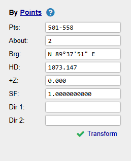
About: Is this the point I’ll rotate about? In this case, that’ll be point 2.
Brg: Is this the bearing I want to transform to? In this case, that’ll be point 2 to point 6.
HD: Is this the distance I want to transform to? In this case, that’ll be point 2 to point 6.
Dir 1: What goes here?
Dir 2: What goes here?
If anyone is familiar with Q-Cogo, I would appreciate your help. Please see the attached files.
 field-dog replied 10 months, 3 weeks ago 6 Members · 19 Replies
- 19 Replies

Ok,
If you click on the blue underlined Points it will toggle between options.
I used the Values option and it seemed to work fine.
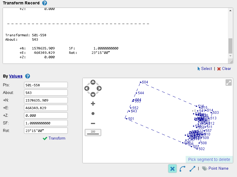
i moved everything from pt 543 to point 2 and rotated around 2. There seems to be 82.8 feet between 541 & 6. I double checked using Traverse PC and it looks the same.

@gary_g
Thanks for the help. Will look it over tomorrow. It’s time for a family game of Scrabble. Did you know that qua and qi are legitimate Scrabble words?
MH@field-dog ohhhhhhh yea.

I love Q-Cogo very versatile

If you have RTK information then project to state plane using your L, L. Forget trying to rotate and translate the assumed XY to State Plane, simply use the underlying geographic data to project to state plane.
Unless you’re saying that the RTK is some assumed L,L. That shouldn’t ever happen with modern equipment and all the data sources that are available.
I calculated 57 points on an assumed coordinate system using N = 10,000 and E = 10,000 as the first point. I collected 24 points (property corners) using RTK on the Florida East SPC grid in the subdivision that I’m surveying. I want to hold a block corner (original plat CM) and a PC (original plat CM), both on the same line, so I can translate and rotate my 57 calculated points onto the SPC grid. I need to do this so I can search for more property corners with my rover.
Are you saying to simply recalculate my 57 points using the latitude and longitude of the collected block corner that I want to hold?
MH@gary_g
My input and results were different.
543 10135.967 9994.205 0.000 COGO
2 1588771.875 474344.034 0.000 CM_4X4
Calculated Points 543(COGO) to 531(COGO):
HD: 1073.743 Brg: N 89°56’32” E
dN: 1.082 dE: 1073.742Collected Points 2(CM_4X4) to 6(CM_4X4):
HD: 1073.147 Brg: N 89°37’51” E
dN: 6.913 dE: 1073.125Transformed: 501-558
About: 543+N: 1578635.908 SF: 1.0000000000
+E: 464349.829 Rot: 359°41’19”
+Z: 0.000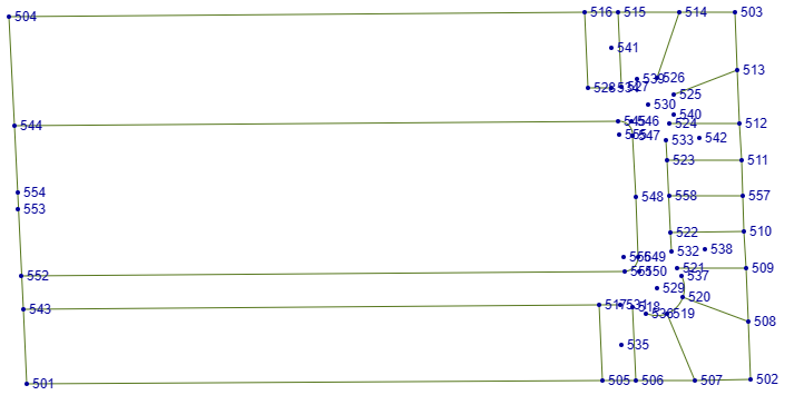 MH
MHOhhhhh wow ! I WILL DOUBLE CHECK TOMORROW,
BUSTED!
I grabbed the wrong point number in my haste !
Do these values match yours now ?
@gary_g
Will check when I break for lunch. I really appreciate your help with this.
MHI have fun figuring this stuff out. I like Q-Cogo, I keep a linnk to it for quickcomps whne workingn in Traverse-PC.
I see your issue, if you have calculated points they obviously don’t have LL attached to them yet.
I would simply put them in a drawing with the desired projection, then align them to my two located points as a block, then unfreeze the block and export the new XY points to my GPS database.
In fact that’s exactly what I’m doing this morning. I located some points on an old NAD27 data base project Thursday. I’m putting it into my new LPD projection by the align command in autocad.
Qcogo looks kinda complicated, but good luck it’s looks like a useful program.

Obviously there is a disagreement between measured and calculated of about 0.6 ft. This transformation translates and rotates about pt. 2 so that the azimuth of 2-6 and 543-531 are the same. Your stake search points should be within a half foot or so based on the measured difference.
Result
543(COGO) to 2(CM_4X4): HD: 0.000
_ _ _ _ _ _ _ _ _ _ _ _ _ _ _ _ _ _ _ _ _ _ _ _ _ _ _ _ _ _ _ _ _ _ _
2(CM_4X4) to 6(CM_4X4):
HD: 1073.147 Az: 89°37’51”
SD: 1073.147 Grd: 0.0%
dN: 6.913 dE: 1073.125
dZ: 0.000_ _ _ _ _ _ _ _ _ _ _ _ _ _ _ _ _ _ _ _ _ _ _ _ _ _ _ _ _ _ _ _ _ _ _
543(COGO) to 531(COGO):
HD: 1073.743 Az: 89°37’51”
SD: 1073.743 Grd: 0.0%
dN: 6.917 dE: 1073.720
dZ: 0.000This transformation translates and rotates about pt. 2 so that the azimuth of 2-6 and 543-531 are the same.
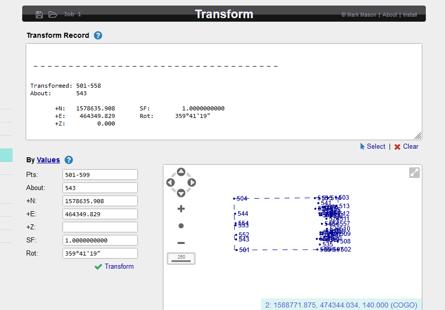
I translated and rotated about point 543. I’m used to using a transform program with different prompts than what Q-Cogo uses. Something like “Choose one point from the old system and one point from the new system.” Old point 543 becomes new point 2. Then you entered the old bearing and the new bearing or just the rotation angle. Some guy I used to work under chuckled when referring to C&G’s Sit and Spin rotation program. He thought the name was funny. I was told to translate first. After translating, it shouldn’t matter because at that point both point 543 and point 2 will be the same. I’m going to test that assumption when I have more time.
MH@gary_g
The attached file isn’t of a type recognized by my iPhone 13 or by my Windows 10 computer. Could you send a CSV, in PNEZD format, file? Thanks.
MH@field-dog It is a comma delimited text file. Open with Excel or Word. I just opened it up on my tablet with Google chrome.
@gary_g
OK. Will try again later.
MH
Really, really good exercise for learning.
If we use Q-Cogo’s Helmert transformation (what the math behind the others is, I have no clue) with its calculated scale factor and again with a scale factor = 1, we get this:
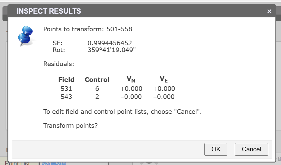
and this:
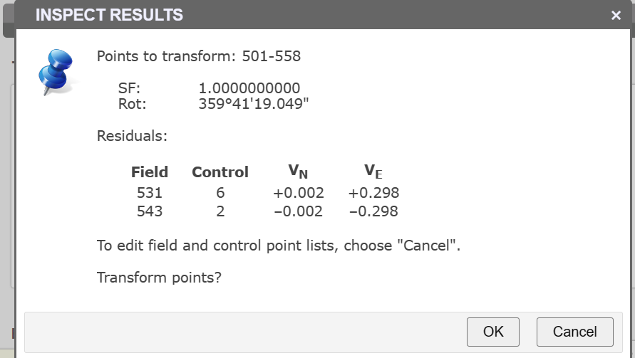
Why do transformed points 531 and 543 match their observed coordinates when the Scale Factor <> 1 but do not match their observed coordinates when the Scale Factor = 1? It’s because a scale factor <> 1 preserves distances in the transformed file while a Scale Factor = 1 preserves distances in the input file.
In this case, the calculated distance from 531 to 543 is 1,073.743 ft while the calculated distance from 2 to 6 is 1,073.147 ft. It seems reasonable to conclude that the input file contains ground coordinates and the observed points are State Plane coordinates.
When the Scale Factor = 1, the underlying mathematics of the Helmert transformation has been told that there is no scale difference between the two systems. If there really is a scale difference, the output coordinates of the control points will not match their input values.
Thus, Scale Factor = 1 may have a different meaning in different contexts.
In this case, where the purpose of the transformation is to aid in locating monuments, it makes no difference.
But the lesson is, know what the input is and know what the desired output is to be.
@gary_g
File successfully opened with Microsoft Excel.
MH


Log in to reply.