
Activity Feed › Discussion Forums › Strictly Surveying › Best Procedure for Surveying UAS Targets for High Accuracy
Best Procedure for Surveying UAS Targets for High Accuracy
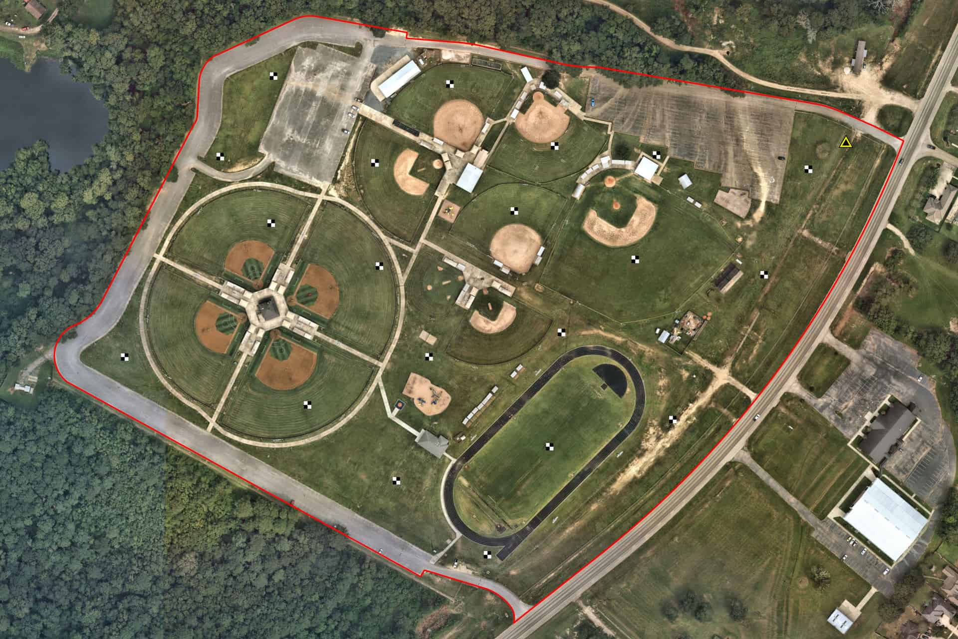
Posted by andrewm on November 19, 2020 at 10:02 pmI’m a civil PE that for some reason decided to enroll in grad school at age 49????. I am pursuing a MS in Geomatics Engineering and GIS through Colorado University – Denver. For my master’s project I want to assess optimum mission parameters for high-accuracy mapping using a PPK UAS (WingtraOne). In order to conduct this type of assessment I need very accurate UAS targets to serve as checkpoints. The site I have selected is about 40 acres and consists of a local recreational ball park. As you can see of the attached map, I would like to place 20 targets throughout the park. The targets are 12″ square aluminum panels w/ a black and white checkerboard pattern. There is a hole in the center for a 1/4″ x 6″ Mag Hub Nail. A current NGS benchmark (DP2512) is conveniently located in the NE corner of the park (yellow triangle). I own the following equipment at my engineering firm:
- Trimble S5 (5″) w/ MT1000 prism
- Trimble T10 tablet w/ Access 2019
- Trimble R6-4 base and R2 RTK rover
What would be the recommended procedure to obtain the most accurate coordinates of the targets? Ideally the accuracy of the targets (horizontal and vertical) need to be better than the smallest ground sample distance of the UAS imagery. In my case, the Sony RX1RII camera can achieve a GSD of 0.025ft at 200ft agl. This may not be doable with the equipment I have. I can likely borrow a level, or possibly more accurate total station, if necessary.
The targets will only be used as check points to evaluate the accuracy of PPK-only solutions using the Wingtra.
Any tips or advice is appreciated. Thanks!
 spmpls replied 2 years, 1 month ago 16 Members · 64 Replies
- 64 Replies


andream; as you say your equipment is no good enough for the task. At least a 1 second inst. with a +/- 1mm edm might be what you need.
Do you have some type of adjustment software? Do a pre-analysis first. Then if it passes do a Least Squares Adjustment.
Also the location of the targets will have to be changed( I will explain more on this later and before you do anymore on this job).
Make the NGS benchmark one of your Targets. Do you have any scale on this job yet (is the track a regulation 1/4 mile track?).
Looks interesting.
JOHN NOLTON
andrewm; I have one more question which I left out of my above post. It looks like this park is near level (with the track and base-ball fields.
I am sure you want to test the WingtraOne for elevation also. Can you get on top of some of the buildings? At the left of the photo you posted
there is 4 base-ball diamonds, What is the structure that separate’s them look like from the ground.
JOHN NOLTON

A quarter mile and 5 seconds is 0.032 foot, so you won’t get there with minimal measurements and a 360 prism on a pole.
It might be do-able with that instrument by using LOTS of redundancy, and prisms on tribrachs. 2 Direct and 2 Reverse on all angles, multiple routes through the targets, and least squares fitting. Lots of work. I recommend the pre-analysis suggestion made above to check out the possibilities.
.
Agree with Mr. Nolton that if you can find a point from which to observe all the targets from above, that’s the ideal scenario.
Do you have access to StarNET, or another similar program that can do preanalysis? That’s the only way you’re really going to figure out how many observations you will need to make.
If I had to do this solo, I would probably run a traverse starting and ending at the BM, trying to run through as many of the targets as possible, but if not trying to at least observe them from multiple stations. Turn a couple sets to each target. Best would be prisms on tribrachs as Bill suggests, but you MIGHT be able to make it work with the MT1000…
Then I would set a base up on the BM, start an RTK + logging session, and then take that rover and hit all the targets with 2x 1-minute RTK observations, turning your rod 180 degrees between each observation. If you can do that whole routine twice during the same RTK session, do it. (Meaning, hit all the targets with double observations, then go back to the first and do it all over again.)
All the vectors and TS observations go into TBC or StarNET. If the BM has a good horizontal position, use that, otherwise run OPUS on the static data from the base. Fix that horizontal position plus the published vertical and run a minimally constrained adjustment. Should get you pretty darn tight. Multiple GNSS RTK at different constellations + multiple TS sets to all points in the network has yielded excellent results for me in the past.
“…people will come to love their oppression, to adore the technologies that undo their capacities to think.” -Neil Postman
I have Trimble Business Center Survey Advanced.
I haven??t been to that park in many years, but I may be able to place a few targets on top of the dugouts. I??ll have to look and see what??s possible.
There is a decent amount of relief in the large parking lot on the north side. From the woods south to the high school baseball field, there is about a 10 foot elevation difference. That??s a lot for south Louisiana lol
What accuracy do you think is reasonably achievable? If I can??t test 200ft agl, that??s not a huge problem. I may eliminate altitude as a variable, as with all other parameters being equal, lower should be more accurate. I typically fly at 400ft agl, which results in a gsd of 0.05ft.
If that is a more attainable accuracy, I would rather spend more time changing other flight parameters instead of altitude as well.
I??m looking to vary base static collection rate, image forward and side overlap, camera shutter speed and aperture.

Fresno State University is wrapping up a 3 year research project on this very topic in a couple of months. The results should be published early next year. I wasn’t the lead on the project for our agency, but I do know that rigorous leveling was done on the target array, which was extensive. Once the control work was completed on the targets, my contributions were no longer required, and that was a couple of years ago. The intent is to morph the findings, including the analysis of various sensors, into standard specifications to be used in future contracts.
Thanks for the information. I will keep an eye out for the paper. My project is much smaller and focused on my specific drone. I am taking this opportunity to further learn its capabilities that will help my business. I??m not doing a peer-reviewed thesis or dissertation, but I would still like to do as good a job as I can. And as we??ll all agree, if I don??t do the surveying properly, the results will be meaningless.
I have a question:
What is the test situation where the Sony gets a 0.025′ GSD?
I worked for a major global orthophoto lidar company and in 2018 with ‘real’ systems we could get 3″ gsd with our gear and 1.5 was coming into workflow, but our IMU cost 85000 dollars not to mention the planes etc.
Is this real gsd or on the fly gsd. I’m just trying to figure out how it gor so tight in such a short period of time, so inexpensively.
Just curious.
And bravo! I’m 50 chasing my PLS and schooling again.
Let the youngsters fear the tenacity of silver haired curve thumpers…. Woohoo!

Traversing through the points with your Total Station would be the most precise manner of positioning the points, and levelling through the points is the most accurate way to transfer elevations, but the GPS will tie the points to a degree of precision that is much better than your UAV ground sampling distance. As others have suggest, multiple measurements with time offset.
One thing that has not been mentioned is the effect of the centering error of your occupations on final precision. Setting up over the points on tripod/tribrach mounted points will improve the centering error, and therefore the results. Vectors produced from static GPS observations, post processed, will be of slightly better quality than RTK vectors. Nevertheless, I think that an RTK program will produce satisfactory results.
Whatever you decide to do, adjust it in your TBC. That will give you a report on relative accuracy, which you can compare to your GSD.
The WingtraOne has a 42mp Sony RX1RII full-frame DSLR camera. It can achieve 0.025?? gsd at a flight altitude of 200 ft agl. I typically fly at the maximum permissible FAA altitude of 400 ft agl, which gives me 0.05?? gsd.

NSPS procedure for determining spatail data accuracy requires the equipment used to test the dataset be 3 times more accurate than the final accuarcy statent. Therefore as others have noted suggest renting a 1″ instrument with .5mm edm.
I notice this problem often on large sites requiring high accuracy anchor bolt surveys by others using 3″ instrument with 2mm edm. Currently on a few 700ft long buildings. Surveyors differ by 0.07ft due to poor procedures.
My local Trimble dealer has a demo SX10 that I can hopefully borrow, or at worst rent. That??s probably the best I??ll be able get my hands on. I doubt they have a S9 HP in their demo or rental fleet, but I??ll look into it. The SX10 is 1? with 1 mm + 1.5 ppm edm.

The Geomatics Department at the University of New Mexico did a study along these lines a few years ago. They might be a good resource for you.
@andrew-clark
Thanks, I’ll look into that.

First of all, you should be able to get a fully working version of StarNet for a demo time period…either way, it is worth investing in.
Second, working through the tutorials in Starnet is VERY worthwhile…You should be able to do it in a weekend. This won’t make you an expert in the software, but I am guessing you already had a class in statistics and some sort of an introduction to least squares in your undergraduate studies.
Third, StarNet will enable you to answer the question of how to design your network, as it provides prediction and planning tools for control.
Fourth, you must have some sort of statistical analysis of your control in order to compare with the the photogrammetry data, if not StarNet, then something.
If I was doing this for published study, I would likely buy/beg/borrow/steal the best equipment I could for the control, including Post-Process Static GNSS observations on every point that will stand it. Perhaps multiple traverses, perhaps with different equipment. Feed it all into your analysis software with the appropriate parameters for your observations and equipment.
Then I would create multiple data sets on different days using the drone. Perhaps 3, but better 4 or 5, in case you have some reason that a data set is no good. I would run it through three different software, but my suspicion is that most of them do the same thing using the same basic engine. Perhaps the Australian software (forget the name), Pix4D, Carlson (cloud), ACAD (cloud), Photoscan or Photomodeler.
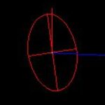
Then I would publish the comparisons of each resulting set. You can even use the analysis software for that. Most interesting would be to compare the error ellipse between a point in the photogrammetry sets (held cold from PPK), with the final error ellipse of your base control. My guess is that you will find that the current photogrammetry software is pretty dang good at resolving this stuff. Depending on relief and topography and other aspects it may be that your relationships (not withstanding scale and overall accuracy to a datum) between the points will be the most accurate using the photogrammetry observations.
I would expect at least a week to two weeks of field work, and maybe double that in the office, plus what it takes to write the report.
-All thoughts my own, except my typos and when I am wrong.Interesting…was the data collected over a short time period?
Or do you also model the movement by periodically revisiting the control (given the instability of California)? No, that is not a P&R remark!
-All thoughts my own, except my typos and when I am wrong.The test facility is small enough, and in the stable foothills, that any secular movement over time would likely be somewhat cohesive, although it would be worth verifying at some point. Vertical stability is not an issue at this location. The initial control work was done over a relatively short period of time, so even in California, any movement during the survey likely resulted in very little “noise” in the accuracy estimates.
Log in to reply.