
Super Tall Geodesy
In the early evening of Friday, June 14th, 2013 seven men met in the warm darkness of a busy city sidewalk and discussed the work that was scheduled for the night. All trades had left the building and all elevator operations had ceased except for the one exterior hoist. That hoist was at their disposal.
The evening temperature was projected to be constant and the wind less than 5 miles per hour.
In the previous days the three crews with their total stations had visited a calibration base line to determine constants and scalars, and the instruments collimated for horizontal, vertical, and level on the construction site. The three levels were pegged and collimation errors determined. Targets, plummets, plate levels and tripods adjusted and the three optical plummets adjusted looking down or up from a bridge between the 15th floor of two buildings on Broadway.
Equipment, procedure and a realistic estimation of error propagation are more important than any adjustment technique. But even a rigorous theory cannot completely describe reality.
A city like New York is never quiet at night and the sidewalks are constantly occupied as people move about. It’s not rush hour by any means, but cute couples, cops and silly drunks keep it entertaining. The pretty giggly gaggles of girls tend to impede the progress the most, for some inexplicable reason. Most, at night, are polite, cheerful, and empathetic as they enjoy their night and as we obviously labor on some mysterious but nevertheless significant project.
Semi-serious men are doing strange things with extravagant equipment in the dark.
We share the sidewalk happily, for what passes by and how we interact will provide numerous hours of entertainment later.
But now, specific instructions have been issued.
A minimum of eight sets were to be successfully obtained in the next six hours of astronomical twilight. Seemingly an easy objective, it required that instruments, targets and levels be reset after each set to randomize centering, leveling, and height measure errors. The levels were bucked in to the instruments and targets between each set, with the height mark carefully split between the inclined crosshairs of the level, so heights could be determined with micrometers. Eccentric targets and instruments carefully arranged so lines of sight crossed, providing identical atmospheric conditions for the significantly inclined sight lines.
At the northernmost station an unattended delivery truck obstructed a line of sight, so Agency police were contacted and an Agency tow truck from the Tunnel arrived and moved the offending vehicle off the line after a half hour delay.
Meanwhile, operations had begun to the south.
Strict instructions were issued as to how a successful set was obtained. After four sets the mean was calculated, as well as the standard deviation and a list of Chauvenet constants provided so a rejection criteria could be calculated in the field by each crew chief. After six, eight, ten and twelve sets the criteria were recomputed and outliers detected and new sets observed if necessary. I’m sure I will take some criticism for not using a more rigorous approach, however, this method requires nothing fancier than a scientific calculator in the field and produces results compatible with more stringent test methods.
Two men attended each backsight, instrument, level and eccentric target. And each required resetting, releveling and remeasuring of HI and HT with the level between each set. A considerable amount of work for a mere eight sets.
As the sun broke the horizon on June 15th and the high eastern face of the building began to rise in temperature, the nights work concluded.
Now, the calculations would commence and geodesy, gravity and geometry would dictate the results.
The magnitude of each correction to be considered is small. However, there is a tendency for each to accumulate and systematic error, considerably more harmful than random error, must be accounted for and corrected.
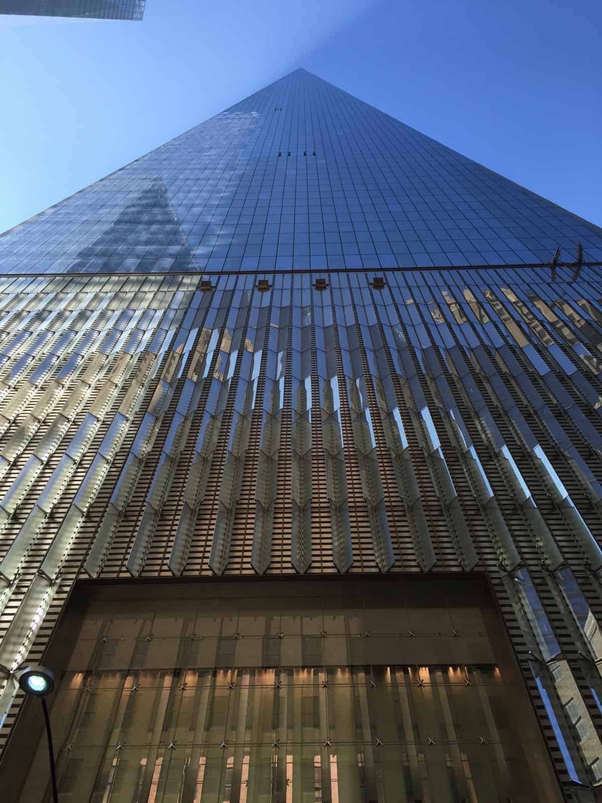
Our trig pillar and test bay.
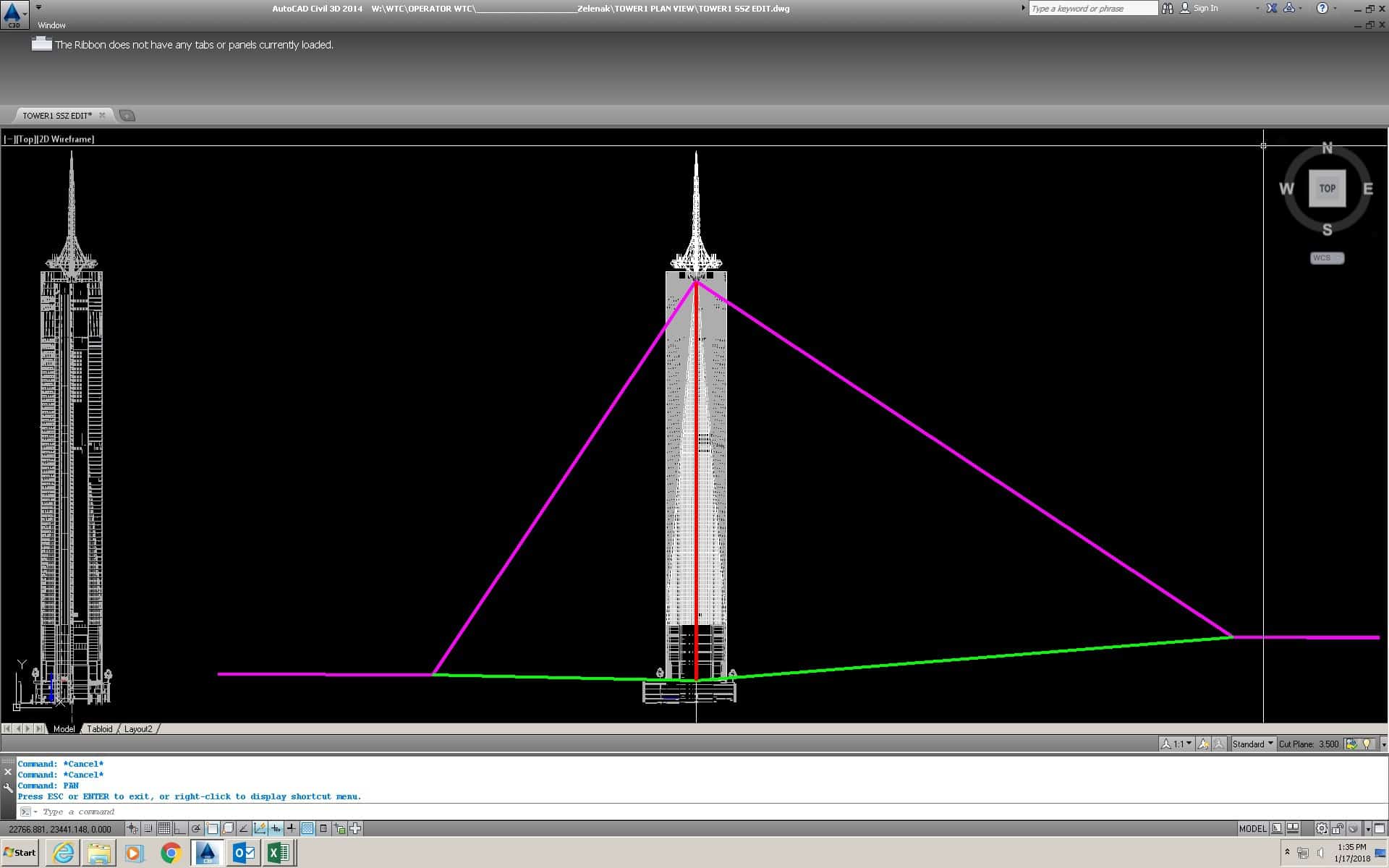
The traverse to the lobby, the simultaneous reciprocal zenith roof traverse and the optical, laser and mechanical plumbing to connect through the shaft cells.
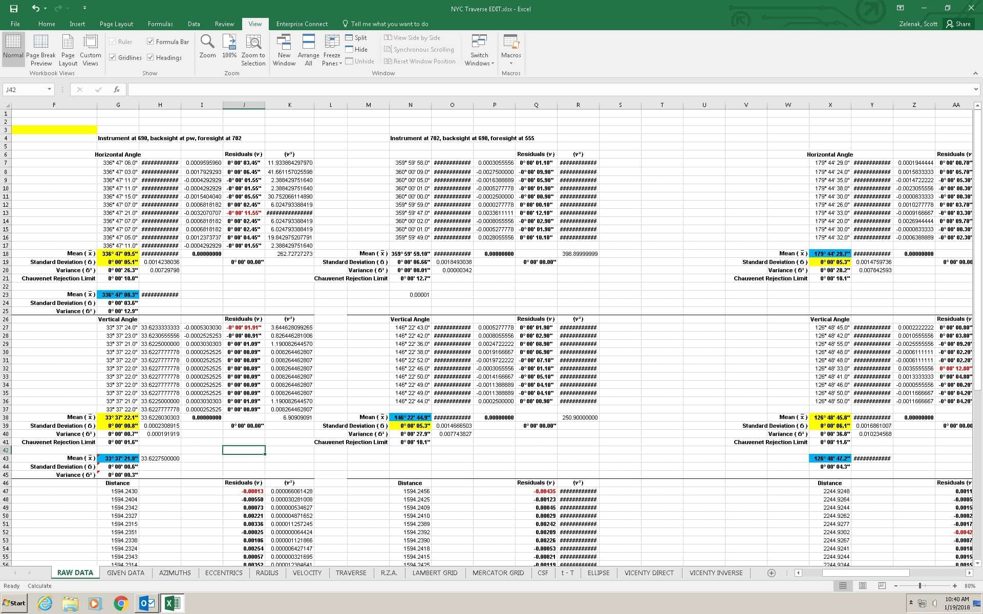
The reduction of all this data requires some manipulation. First we weed outliers out of the raw.
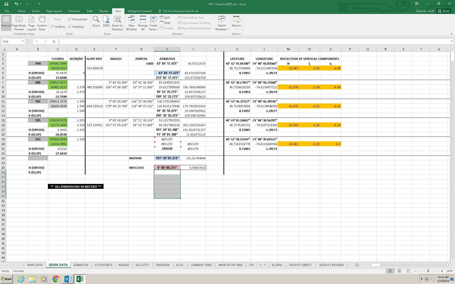
After crunching through the raw, we gather some known data and run some preliminary computations and check the angular misclose.
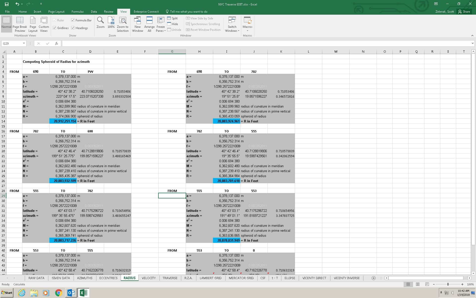
Next we compute our radii on the ellipse in the azimuths required.
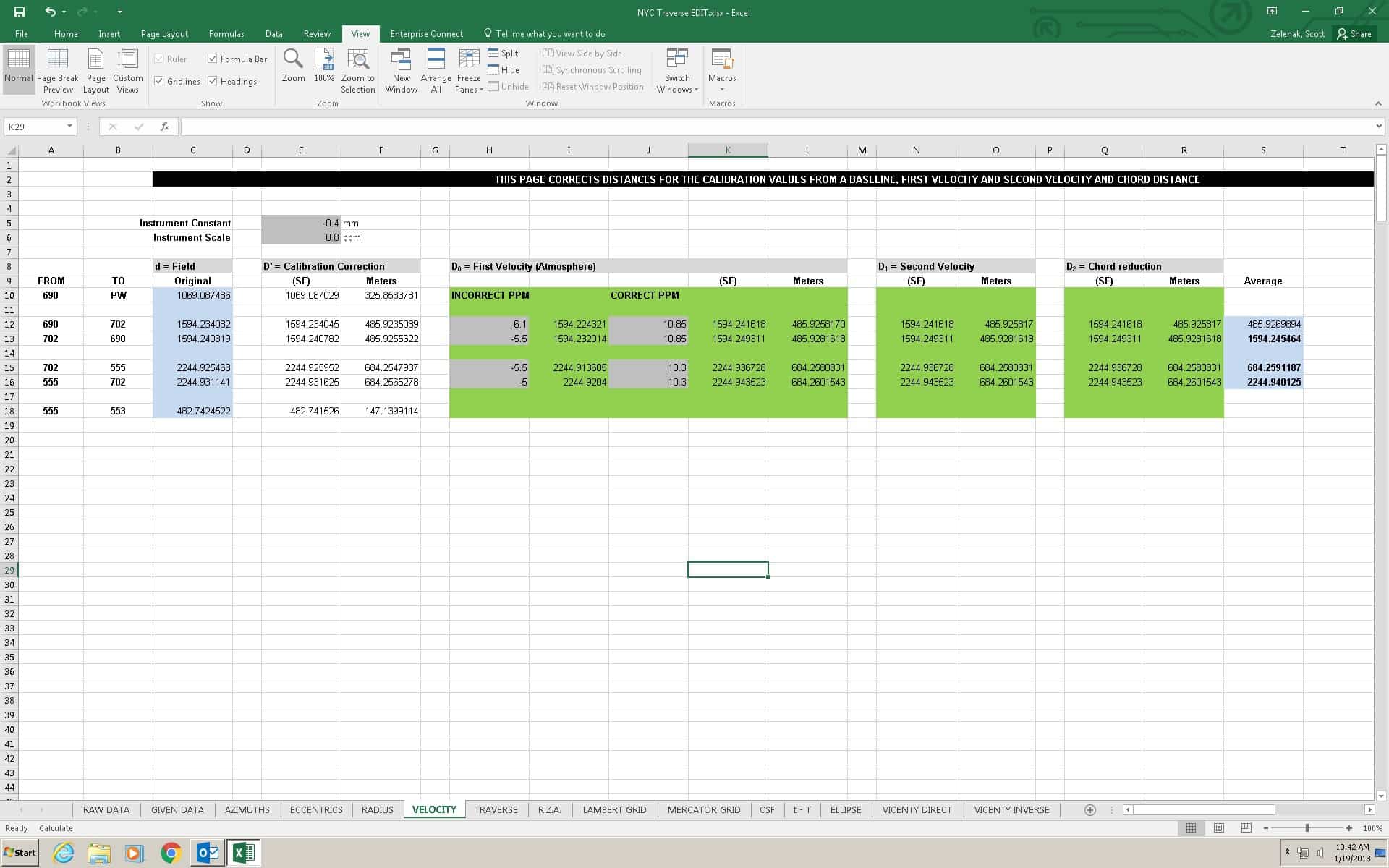
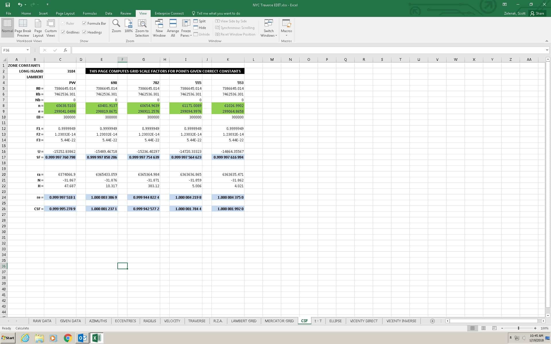
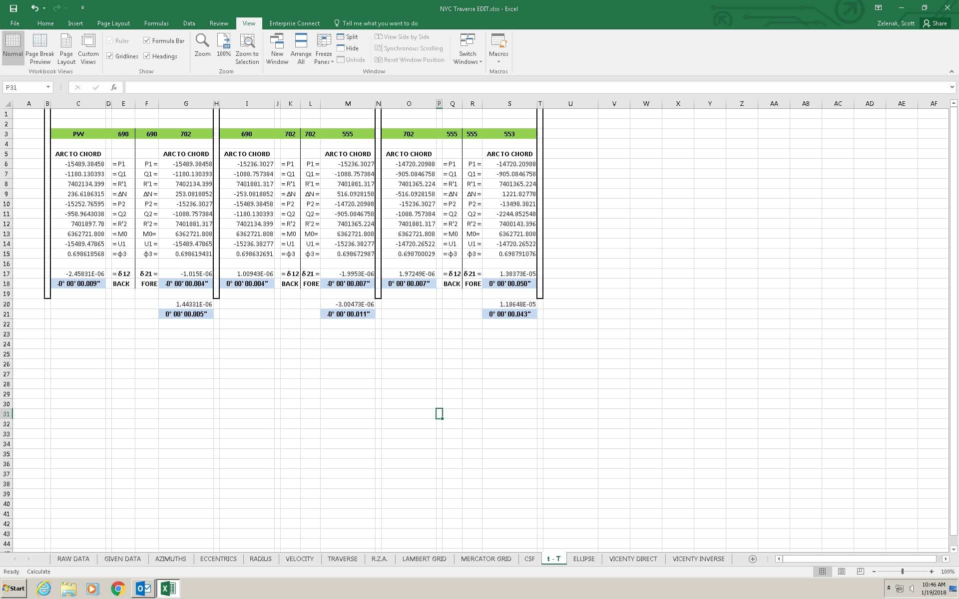
Now we can also apply corrections to the distances for the constants and scalars computed on the calibration base line, and correct for the atmospheric ppms (which here, for instance, were incorrect in that they didn’t average between the ground and the roof stations) and second velocity and chord.
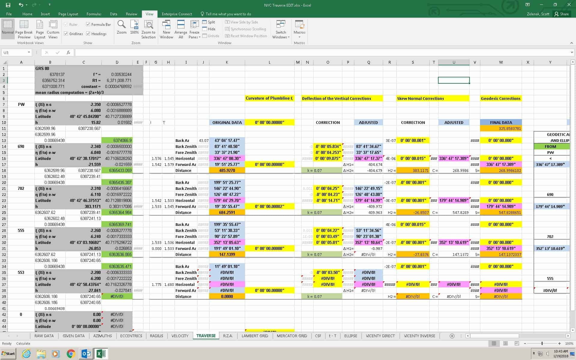
Now we can reduce our traverse, making corrections along the line for curvature of the plumbline, deflection of the vertical, skew normal, and the geodesic.
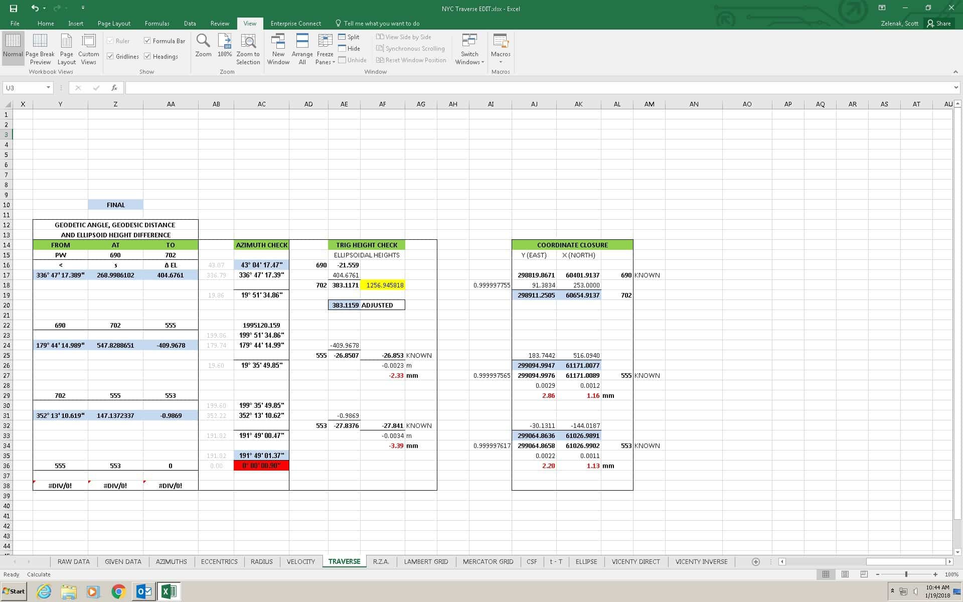
And here we have our ellipsoidal data, and we do another azimuth closure, check our trig heights, and our coordinate differences.
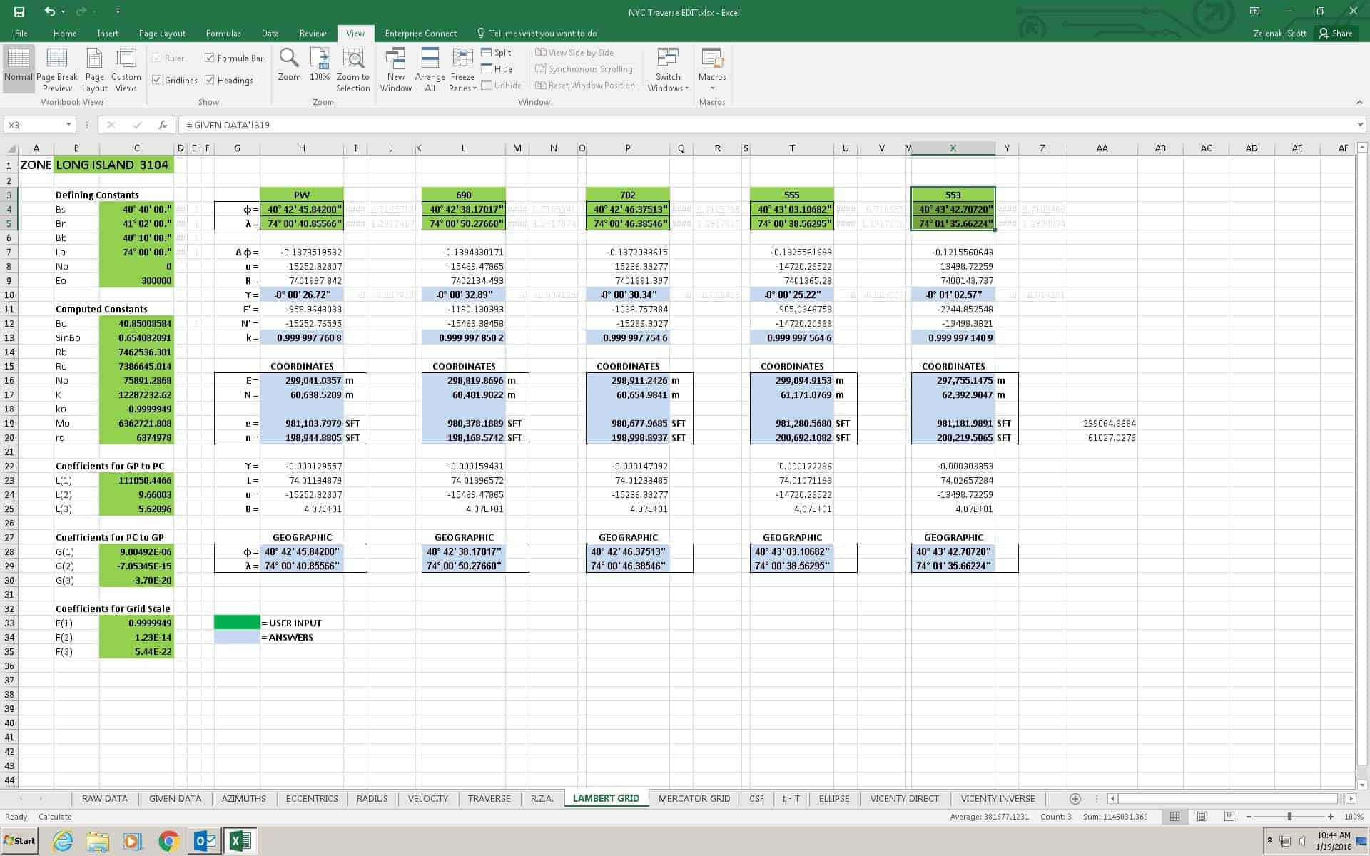
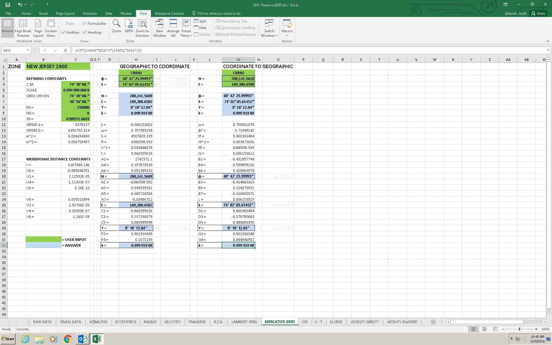
We can now compute constants and variables for our projection.
Now, after using the plumbing to connect the roof and lobby traverse we can use a concept borrowed from monitoring to determine if our plumbing closes and the roof point and lobby point are identical. The monitoring concept uses the coordinates of each point, its associated error ellipse and some computation to determine if the points are identical.
And…”we missed it by that much.”
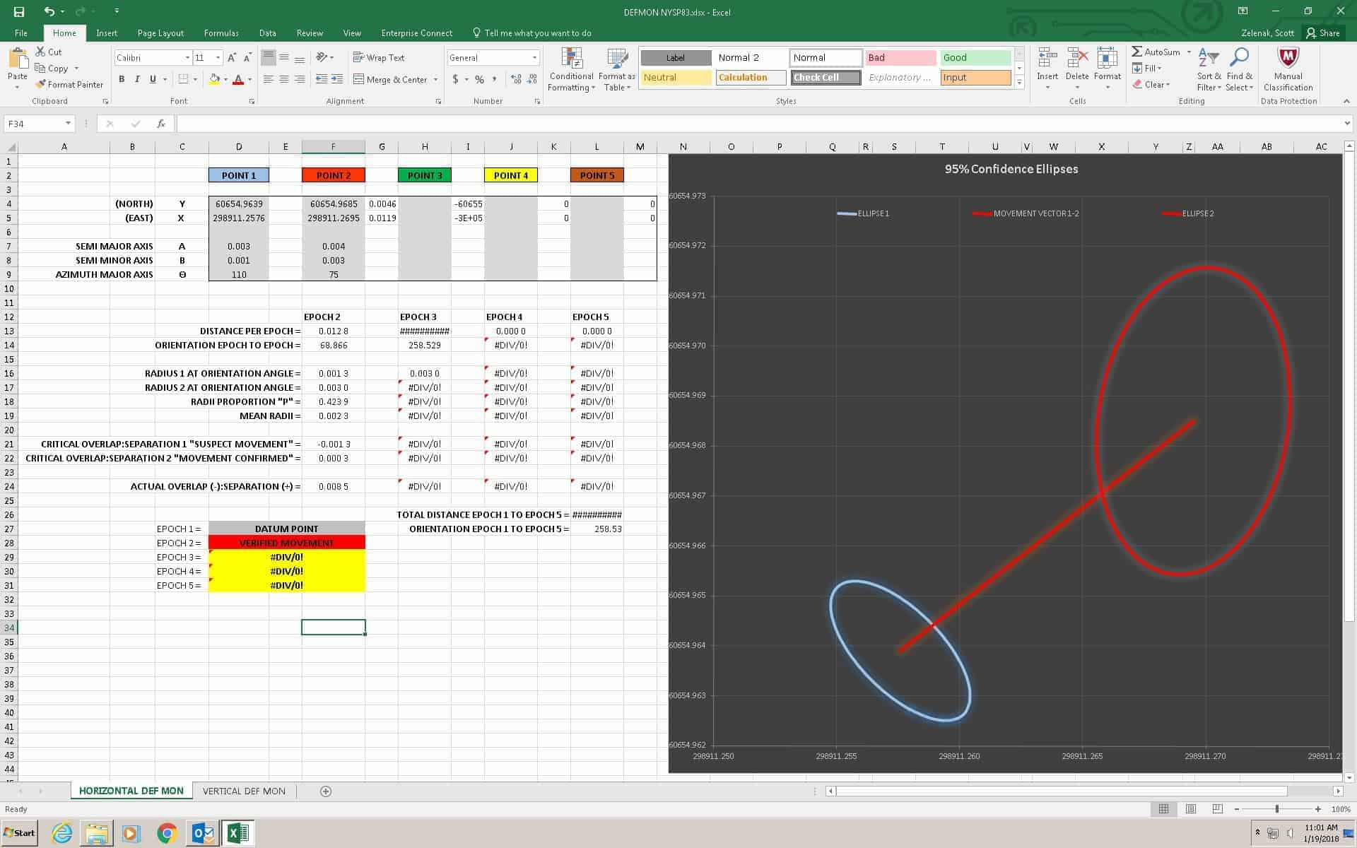
[Insert appropriate expletive]!
So what have we done wrong?
Well, we haven’t gone far enough.
There are many things to consider in a plumbing operation of 500 meters.
Most notable, are the corrections for convergence of the plumbs and deflection of the vertical.
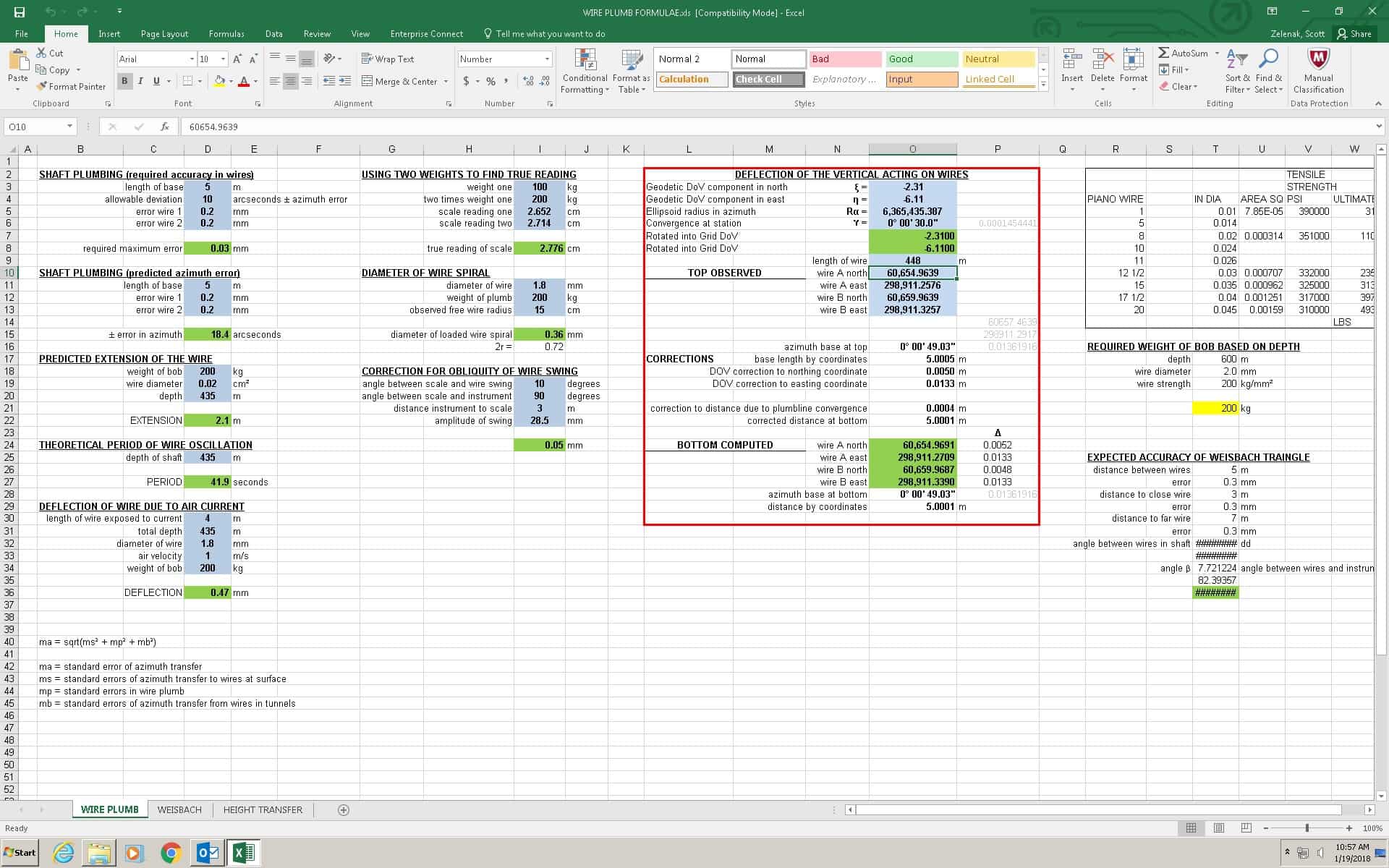
Deflection of the vertical, which is often thought of as a difference of position on the face of the earth between astronomic and geodetic coordinates, is also the angle between the ellipsoid normal at a point and the direction of gravity at the same point. And it’s components (xi and eta) along with our plumbed dimension provide enough to compute the azimuth of this deflection and its linear effects.
Yes, we adjusted our lobby and roof traverses for the deflection of the vertical, and so too must we adjust the plumbs which obviously are not normal to the ellipsoid but collinear with the direction of gravity. So we take our deflection components (given in geographic terms and converted into grid values) and compute the total deflections at the bottom and use them to correct our roof coordinates.
Now, how’d we do?
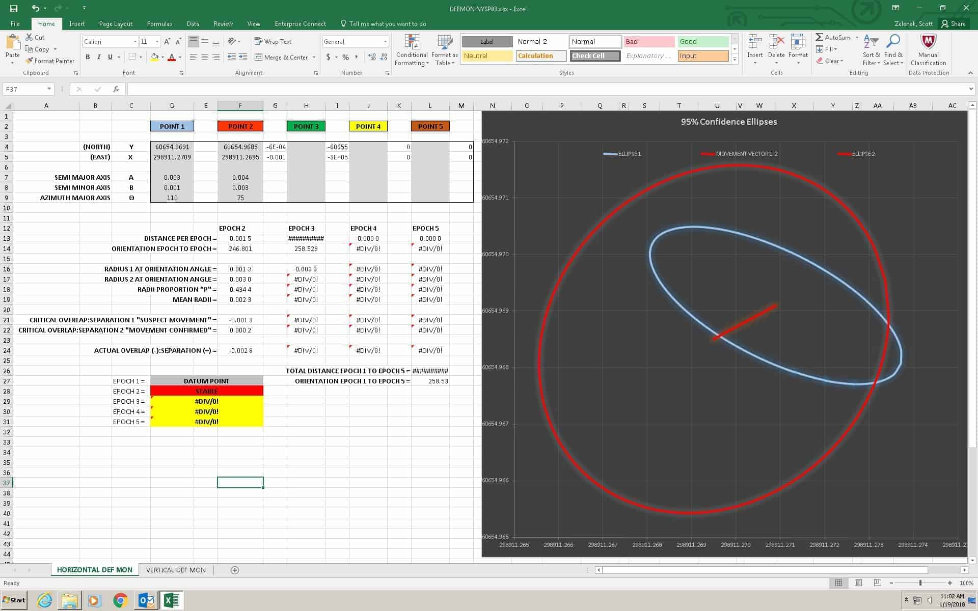
Ok, life is good again.
Now for some sidebars.
I hope NGS addresses this in 2020.
And, Nate I believe, asked if anyone ever used a 500 foot tape. I can say, “No.”
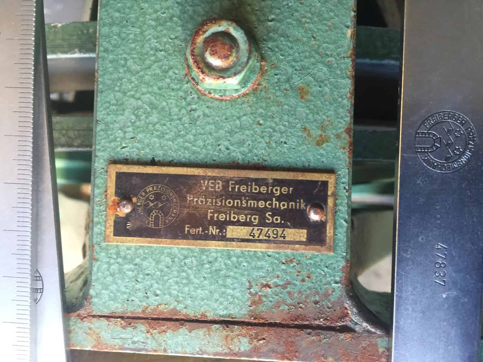
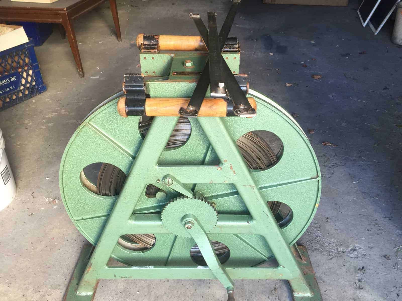
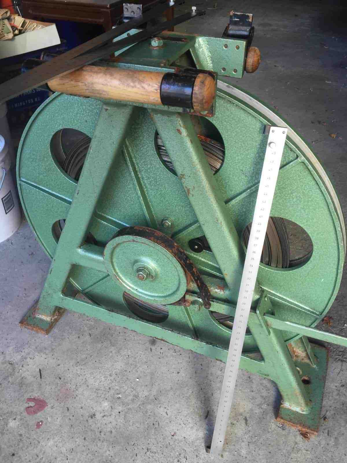
But how many people use a 500 meter mine shaft calibrated invar tape?
That’s 1,640 feet on one reel. We used to call it the “quarter miler”.
Enjoy.


Log in to reply.